
Hornloaded Subwoofer
|
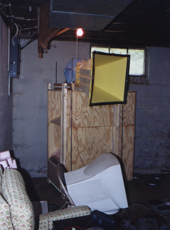
For roughly the last three years, I have been planning, designing, studying, and pondering how best to implement a high performance subwoofer in my music reproduction system. That the system would be designed and built by myself was a foregone conclusion. I just like to build things! Now the only question was which type of alignment to use. Every since I started learning about sound reproduction, I have been fascinated by high efficiency systems. It seems like such an elegant method of achieving the desired goal. This led me to first try high frequency horns. Liking what I heard and reading various impressive descriptions of the sound of bass horns on the internet, I decided to build a subwoofer horn. Now the trick was to design something that would still leave me some space to live in. After much design work, I finally settled on an alignment that would give smooth response down to a decently low frequency while still not being too terribly large. The result can be seen at right. |
|
|||||||||||||||||||||||||||||||||||||||||||||||||||||||||||||||||||||||||||||||||||||||||||||||||||
|
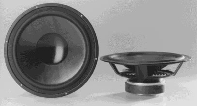
In designing this horn, I was primarly constrained by my budget. This is what led me to base the design around my pair of Peerless 850146 drivers (10" drivers). These drivers are not normally what would be considered horn drivers. They have an efficiency bandwidth product (EBP) of only 56.7 while conventional wisdom would say that a horn driver break 200 on this figure. Lucky for me this 'rule' is typically misapplied - the missing factor is the frequency range the horn is being designed to cover. These drivers have a poly cone and a moderate excursion (9mm). This actually used to be considered a large excursion, believe it or not. The poly cone is probably not a very good feature for a bass horn driver, but it will have to do for now. For a bass horn (and any other subwoofer, for that matter), the more linear volume displacment the drivers have, the better. Plugging the drivers' Thiel-Small parameters into my design spreadsheet (based on Leach's horn model detailed in AES preprint #1405 and elsewhere), I saw that I could achieve fairly high efficiency (~108dB/watt predicted) with these drivers by designing for a very narrow bandwidth - 26.7hz to 100hz. This prediction was supported by simulation using David McBean's Horn Response program. |
|||||||||||||||||||||||||||||||||||||||||||||||||||||||||||||||||||||||||||||||||||||||||||||||||||
|
My other design constraint was that the subwoofer had to be small enough to get up my stairs, around the corners, and fit in my closet. My original plan was to slide the sub into the closet that's in the corner of my room so I would have true corner loading while avoiding the situation of having the speaker pointed into the corner. To meet this goal, I was constrained in both width, height, and depth. At the same time I needed enough area on the side of the box for the horn's mouth. Resolving all this led me to design the box to break apart into two sections. This would allow it to be taller to get the needed mouth area, and the pieces would fit around corners individually when stood on end.
|
|
|||||||||||||||||||||||||||||||||||||||||||||||||||||||||||||||||||||||||||||||||||||||||||||||||||
|
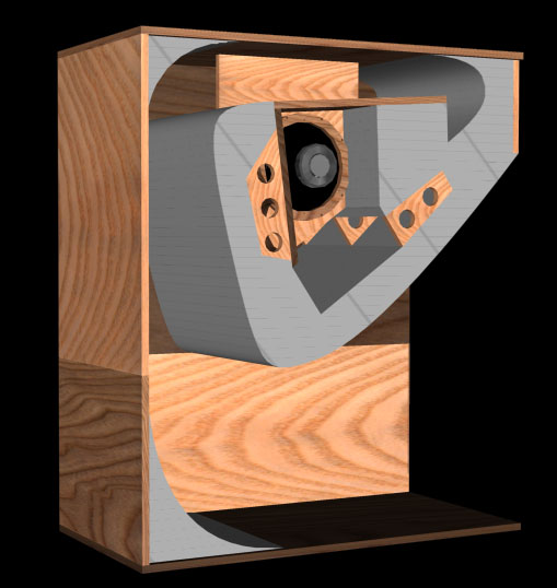
The horn's folding scheme is based on the Servodrive BT-7. It looks like a nautilus shell - the driver is in the middle of the box, and the horn wraps around it. This is a fairly efficient folding pattern and has the additional benefit of only requiring one 180 degree bend - the other two bends are only 90 degrees. While this was not the exact sequence of how I worked through the design of the horn, the above thoughts should give an idea of why I did what I did in this project. The rendering above right is from the design phase of the project - it's an AutoCAD solid model that I made to visualize the box. The picture on the right is the top portion of the box before attaching the second side panel - it corresponds almost exactly to the rendering above (as it should!). The overall size of the box is 22.5 inches wide, 44.5 inches long, and 51.5 inches tall. The 2x4's that I use to clamp the two pieces of the box together make it a little wider and taller. The mouth area is 840 square inches. For a 26.7hz low cutoff loaded into 1/8 space, the mouth area predicted by standard theory is 2557 square inches, so I would really need three of these subwoofers to get the mouth area big enough to make the horn act like it was infinitely large. This is probably what accounts for the drooping low frequency response, which can be seen below. It also probably accounts for some of the lumpiness in the frequency response. However, the horn is slightly longer than 1/4 of the wavelength of 26.7hz, and I would guess that this is why it performs as well as it does. |

|
|||||||||||||||||||||||||||||||||||||||||||||||||||||||||||||||||||||||||||||||||||||||||||||||||||
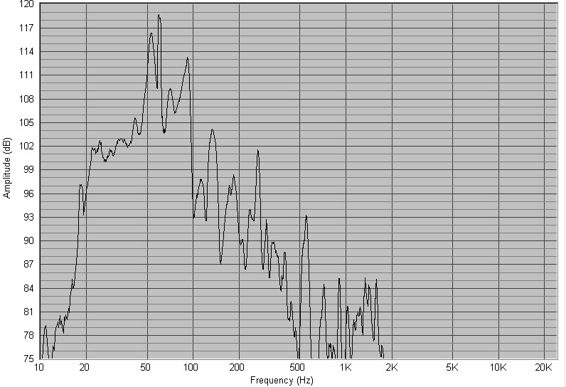
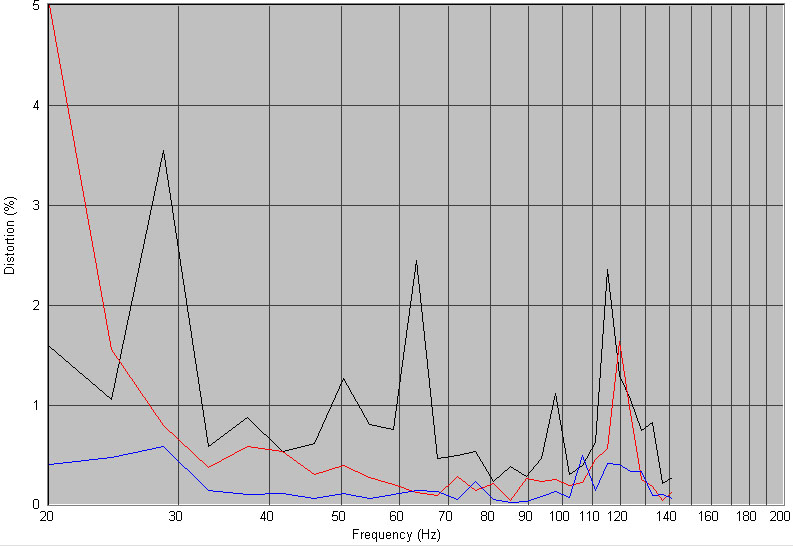
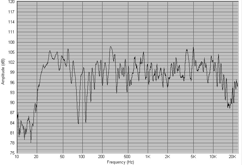
| Even with the undersized mouth, the end result is very nice. In audio-speak, I would describe the sound as lean and tight. It's really not very noticeable until a large event comes along in the bass, but part of that is because I have the system's balance set to a fairly flat frequency response. This would be fine if I listened to everything at live levels but I don't, and at lower levels the bass really needs to be boosted on the low end. From a technical viewpoint, I measure that the subwoofer has a sensitivity of between 100dB/watt/1m and ~108dB/watt/1m depending on the frequency while in the corner of my basement using limited-bandwidth pink noise. Distortion is very low inside the horn's operating band. The distortion plots below are with ~1 watt of power into the horn, so between 100 and ~108dB. (Black is 2nd order, red is 3rd order, blue is 4th order.) The frequency response plot at top right is the raw response with the mic positioned at 1M from the mouth at a 45 degree angle from the wall. The very narrow peak at 60hz is hum in the measurement system. I filtered this response with a 1st order Butterworth lowpass at 40hz and achieved a fairly flat response in the listening position, as seen in the lower right plot (this plot includes effects of the room). |
|
|||||||||||||||||||||||||||||||||||||||||||||||||||||||||||||||||||||
|
|
|||||||||||||||||||||||||||||||||||||||||||||||||||||||||||||||||||||
|
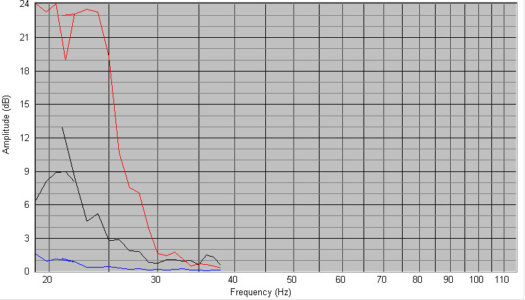
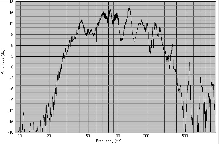
January 25, 2003 Recently, I moved my horn sub out of the basement and installed it in my closet. Since it is now sitting right beside my computer, I took some more measurements of it. The closet the horn is in is located in the corner of my room. The horn mouth points out into the room. In this configuration, the high frequency response is much more extended, leading me to conclude that the depressed response above 100hz as shown in earlier measurements was a result of the horn being pointed into the corner. The plot at the lower right is a nearfield measurement of the sub in this configuration with no smoothing applied. One point to note is that the low frequency cut off measured coincides pretty closely with what would be predicted from the mouth area I used (900 square inches in 1/8th space would be a 45hz cutoff). It also matches up pretty closely with predictions from David McBean's Horn Response program. This makes my previous measurement of extension to almost 20hz in my basement very interesting. The sub definitely did go much deeper in the larger room. Below left is a harmonic distortion measurement. As above, black is 2nd harmonic, red 3rd, blue 4th. I only measured below 40hz to investigate how much eq could be applied to the low end response. As you can see, distortion performance is pretty good above 30hz. These measurements were made at a level where 40hz was approximately 110dB/1m. Looking at the nearfield response plot you can then get an idea of the level of the other frequencies. One interesting thing to observe on the distortion plot is that the 3rd harmonic increases much more than the 2nd harmonic at low frequencies. It seems that my push-pull woofer mounting is working pretty well to cancel even-order distortion components. |
||||||||||||||||||||||||||||||||||||||||||||||||||||||||||||||||||||||
|
|
|||||||||||||||||||||||||||||||||||||||||||||||||||||||||||||||||||||
Copyright 1999-2004, John H Sheerin
Click here to return to my home page.