4-way Stereo System
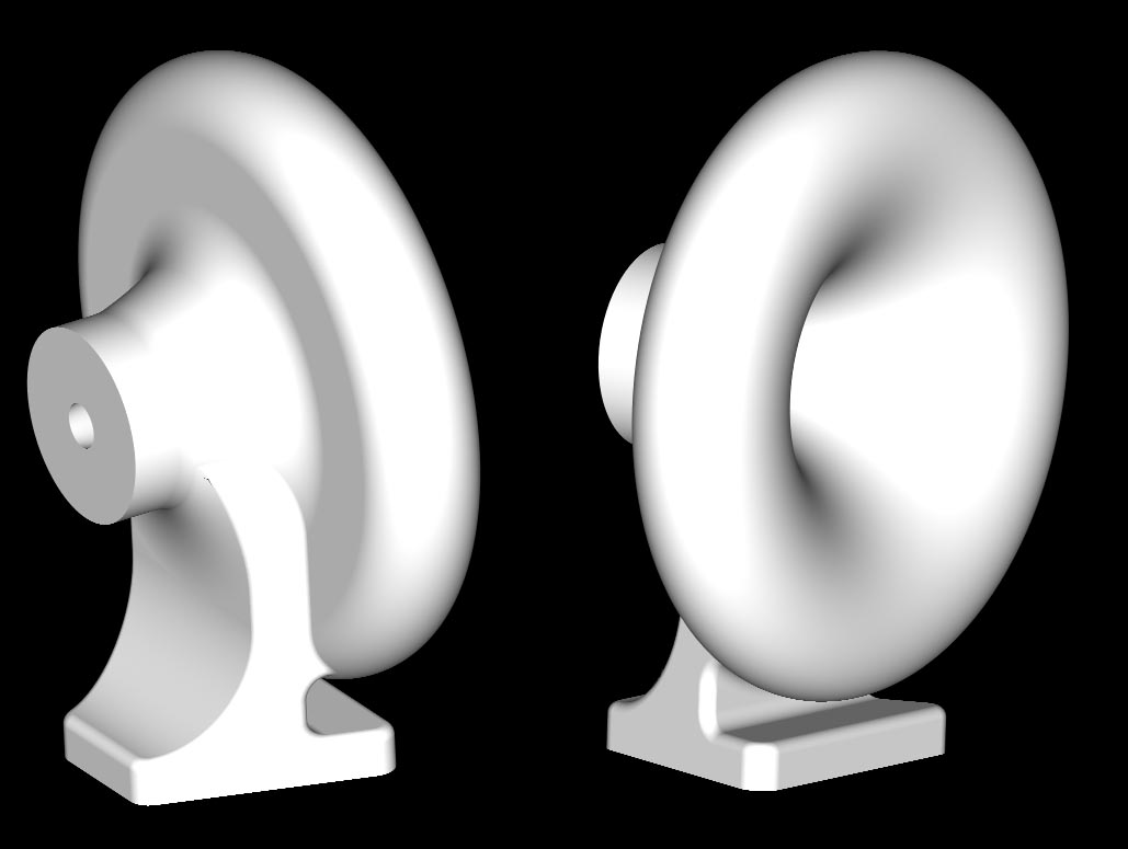
I started designing a new audio system for myself in 2007. It would be a horn-loaded system, at least in the high frequencies, and it would center around JBL's 2435Be 3" dome, 1.5" exit, neodymium magnet, low profile compression driver which I had bought a used pair of from Ebay. This would be mounted to a LeCleac'h horn I would make to cover the midrange. I measured the expansion rate of the 2435 through its phase plug and designed a LeCleac'h horn that kept that same flair rate at the throat of the horn. This turned out to be a 385Hz horn with a T of 1.414. I then designed a foot to support the horn, centering it around the center of gravity of the horn with the driver mounted. Here's the horn I designed:
I designed this horn before I had a way to build it. After moving to start a new job, I had a large amount of free time on my hands and used it to research, design and build a CNC wood router to use to build a pair of these midrange horns.
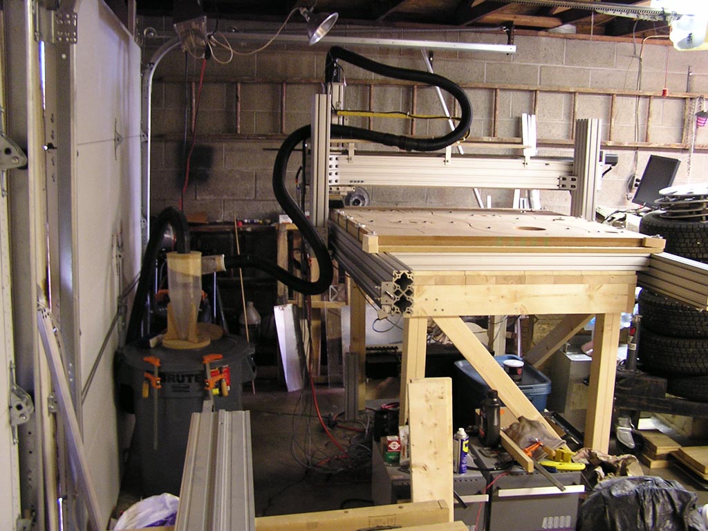
Here's the router after cutting out some of the parts for one of the horns. The horn was sliced up and I cut the slices out sheets of MDF.

Here are the parts glued together, but before sanding:
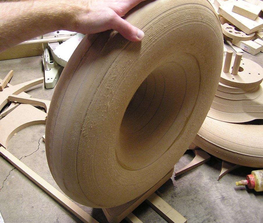
Here it is part way through sanding:
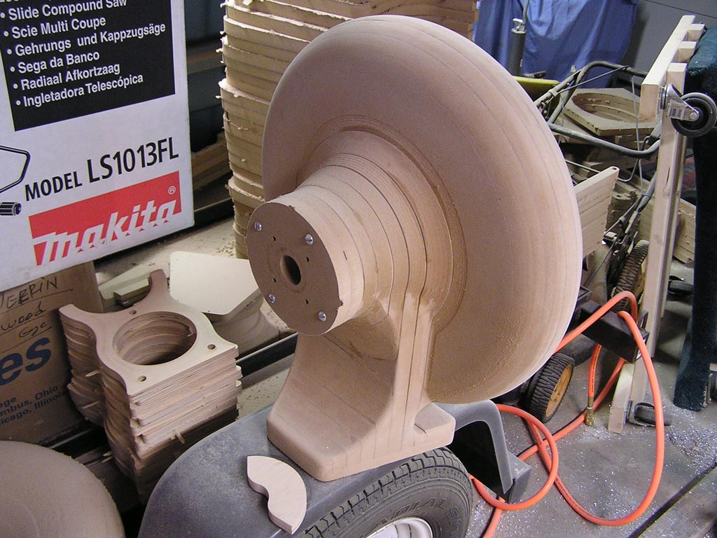
To sand the horn, I built myself a hand-held spindle sander by buying some parts from a Grizzly spindle sander and fabricating a tube and motor mount to attach them to a 300W AC servo motor. This let me reach down into the throat of the horns to sand.

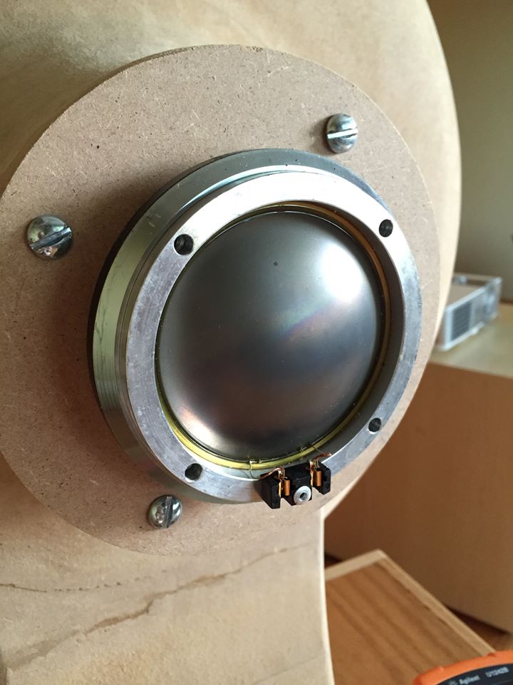
Here's a shot of the JBL 2435Be driver mounted to the horn with the back cover off, checking for damage:
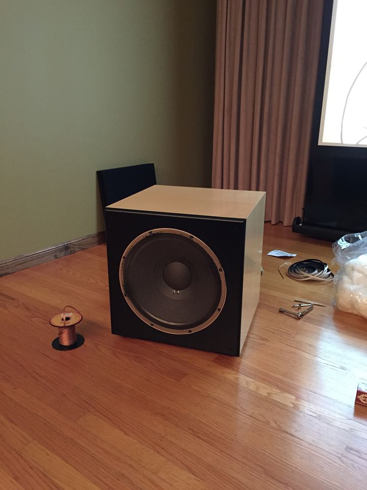
Initially I used one horn sitting on top of a subwoofer I had built earlier using a JBL Sub1500 woofer, a 15" JBL woofer made for a Revel subwoofer. Here I was pulling the woofer out of the box to add some more foam to seal leaks around the mounting bolt holes. I crossed over the system at 500Hz and eq'd everything in-room with DSP. It wasn't horrible, but nothing special. This was in late 2013.

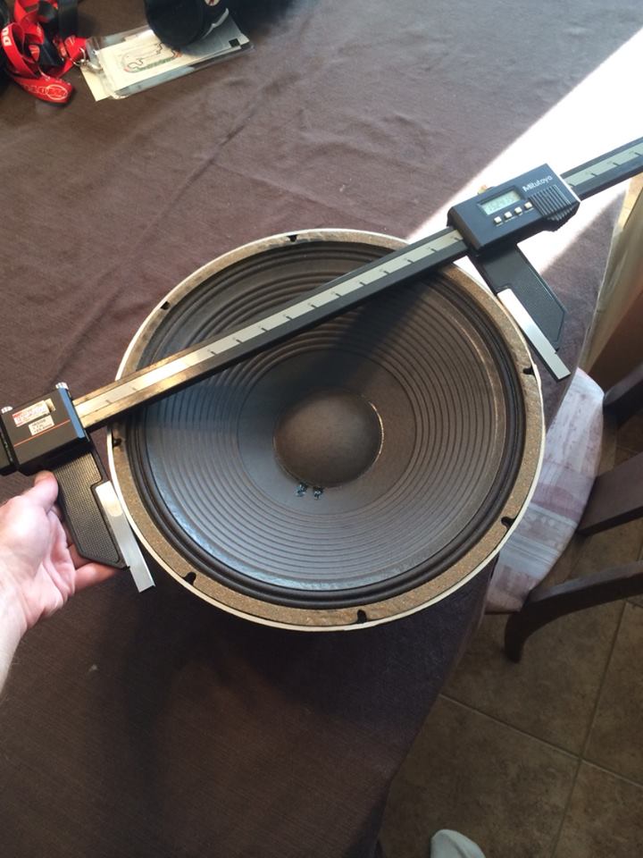
Obviously I needed another driver to bridge the gap between the subwoofer and the midrange horn. I had a pair of JBL 2225 15" high efficiency midbass drivers, so the quickest way to acceptable midbass seemed to be a sealed box. I bought some pre-made cabinets with blank baffles from Parts Express to use as I had just moved again for a new job and didn't have anywhere to do wood working. Here's one of the 2225's as I'm measuring it to figure out what box size I need.
And here's one of the finished boxes:
At this point, the system was still mono as I hadn't finished sanding the second horn and hadn't built a second subwoofer yet. I did more extensive measurement work at this point and got the system eq'd fairly well. I was crossing over the sub at 80Hz, and the midbass to the horn at 800Hz. Now the obvious problem was the horn's response above 10kHz. The polar response narrowed significantly and sensitivity dropped quickly although still fairly smoothly. The system looked like this:
I had also designed a high frequency horn back in 2009. I did a lot of FEA simulation on this during the design process to get a horn shape that would give a directivity that would match up with the top end of the LeCleac'h horn before the pattern narrowed above 10kHz. I used a JBL 2402 ring radiator as the driver and redesigned the horn and phase plug to achieve my goal. This still needs some improvement, but the current iteration works pretty well. Directivity is spot on, but the response could be smoother. I cobbled together a stand for the driver to place it above the midrange horn and retuned the top end of the system.
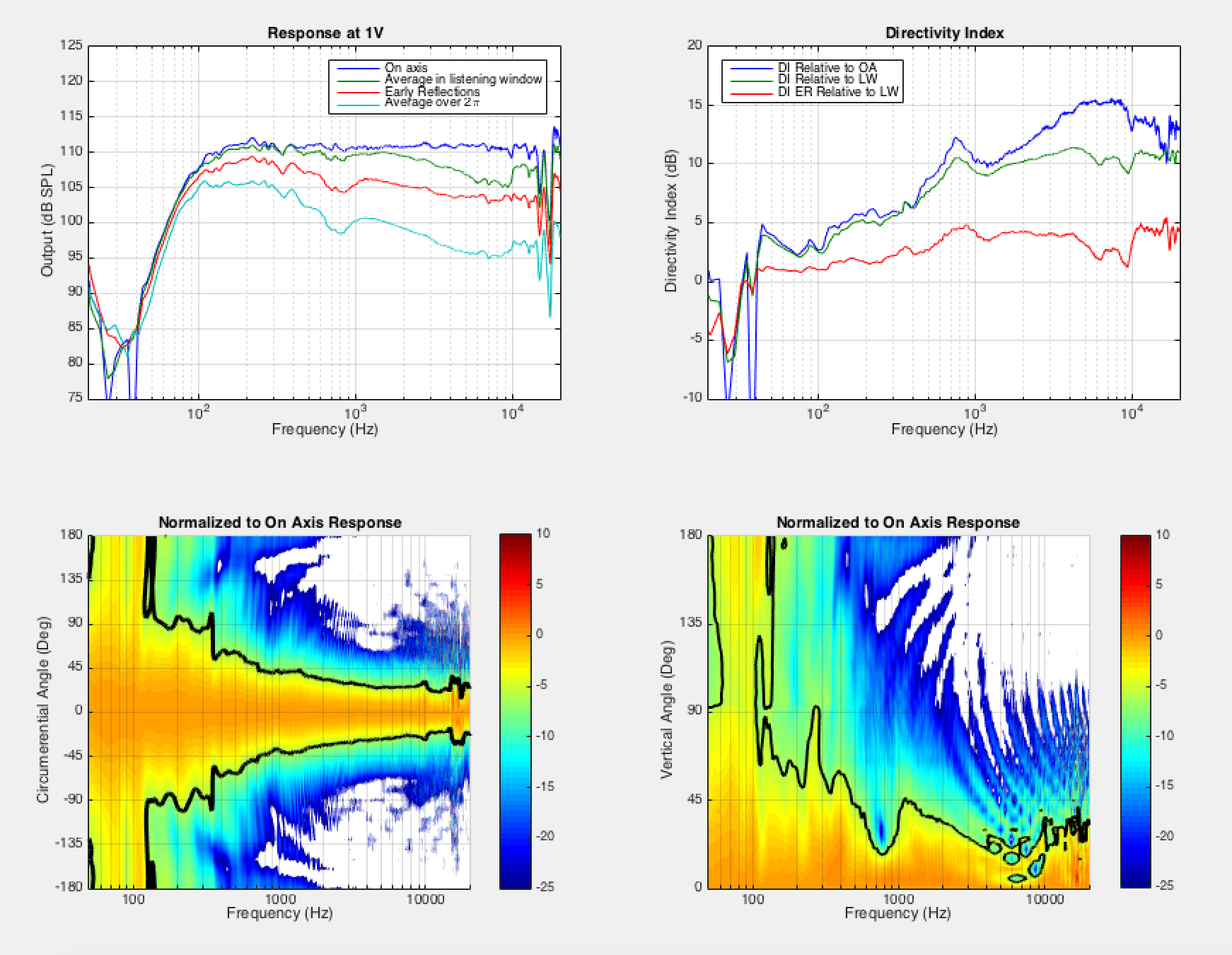
Below is some measured data from the system. This is taken in an anechoic environment without the subwoofer. I tuned the system for flat on-axis response knowing that I'd probably retune it a bit in-room. I picked crossover points by looking at the response of the drivers, the polar responses, the stored energy across the frequency range, the distortion limited max output versus frequency, and the power compression versus frequency. As is usual with horn systems, there didn't turn out to be a lot of wiggle room in where to cross things over. The midbass basically stops working well at 800Hz which is right about where the tweeter works well down to, and the directivity matches pretty well there also. It was similar with the other crossover points. Tuned for flat on-axis response, the average power in the listening window (an area which I might have my head in while normally listening) is fairly smooth, rolling down as frequency increases as you would expect with a high directivity design. However at 10kHz the power in the listening window suddenly bumps up. The early reflections are fairly smooth and lower in level except for around the midbass to horn crossover at 800Hz. The power response similarly has a dip in the response around 800Hz and a bump around 10kHz. Looking at the directivity, there's an obvious bump at the 800Hz crossover. Looking at the horizontal polar map on the left, the pattern looks very well controlled being a fairly constant width above 5kHz and a smooth transition to that point. In the vertical polar map, there's obviously a narrowing of the beam around the 800Hz crossover and a lobing effect around 6-7kHz due to the vertical separation between the midrange and tweeter. Just a note on sensitivity - the response is shown for 1V input to the digital crossover and includes the gain of the amplifiers. Rather than a measure of loudspeaker efficiency, it is a measure of the amount of gain I have in the system.
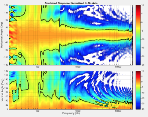
After later simulation using the measured data for each individual driver, I found that I could achieve what I think will be better performance by changing to some non-standard crossover slopes at the same frequencies. The plots below show this simulated response, with the response plots all being normalized to flat on-axis response. I mostly got rid of the hole in the power response at the 800Hz crossover although there is a bit of a bump there in the power in the listening window. The directivity index is also much smoother there. At the crossover to the tweeter, by switching to a lower order crossover with a steeper slope at a lower frequency on the tweeter, I've reduced the jump up in the power in the listening window by a large amount and brought down the directivity index relative to on-axis. The down side is that I've enlarged the frequency range where vertical lobing between the tweeter and midrange occurs. However I have not been able to notice that on the current system as I stand up and sit down, so I think this will be an acceptable tradeoff.

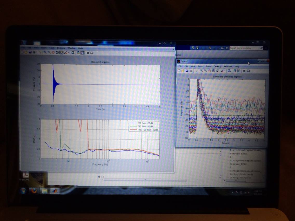
I also measured the decay time (RT60) of the room to aid in tuning the system in the room.
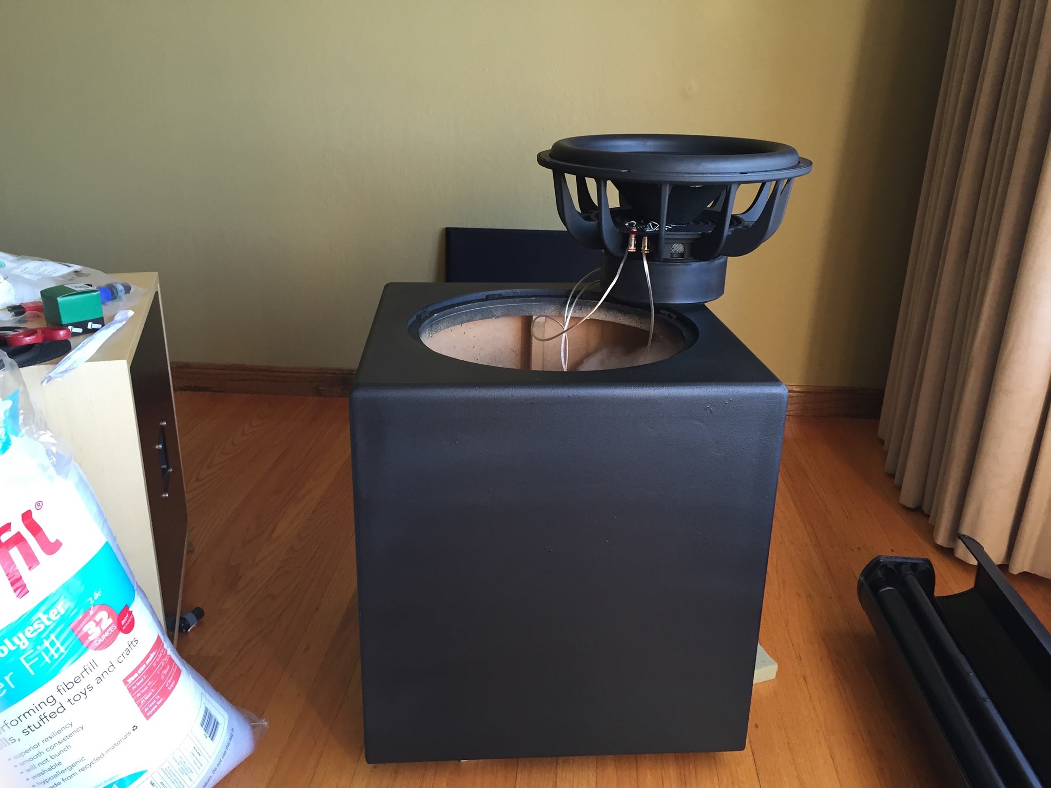
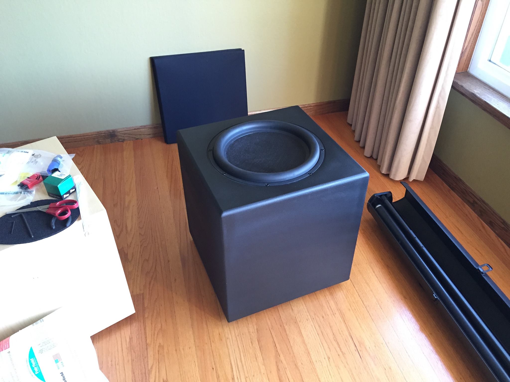
At this point I had one side of the system working and most of the parts to finish the second channel. However I still needed a second subwoofer. This was partially to try out stereo subwoofers and partially for output considerations. The single subwoofer used is the primary output limitation on the system. In an anechoic environment, I would need 4 of the Sub1500's per side to keep up with the rest of the system. However in-room, room gain provides extra output below 40Hz that makes the system acceptable as-is. However the subwoofers still have much more power compression than the rest of the system. Eventually I would like to upgrade both the midbass and subwoofer sections. Since the JBL Sub1500's were no longer available (they were a buyout from Parts Express), I went with a Dayton Audio Ultimax woofer with a flat pack cabinet kit from Parts Express.

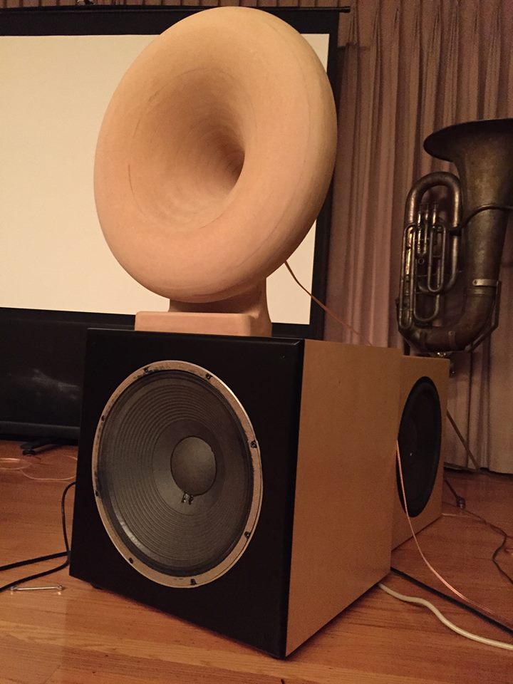
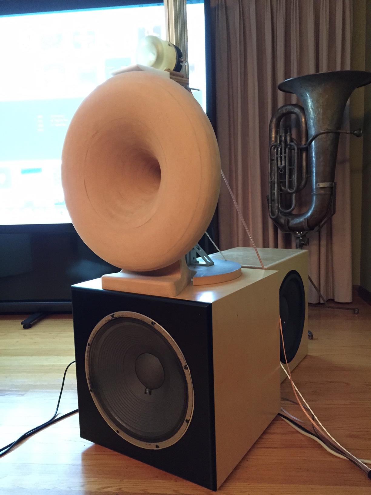
Here is the system as it currently sits. Clearly something needs to be done about that projector 'stand'.

Up until the end of 2016, I had been using a custom DSP integrated into a multi-channel amplifier to control the system. However I wanted to explore more complex filtering using FIR filters, so I started putting together a miniDSP system. I bought two of the miniSharc systems along with 6 Curryman DAC's. I routed the input into the first miniSharc, then ran a stereo output to the second miniSharc. I connected 3 stereo DAC boards to each miniSharc, giving me a total of 12 output channels. After some software updates, this turned out to work quite well. The noise floor was reduced quite a bit and sound quality seems very good. So far I have only duplicated my IIR filters from my previous setup on the miniDSP, but when I get time I will start exploring using the FIR capabilities. I am currently working on a volume control and display using an arduino to talk to the miniSharc, replacing the vol-FP board from miniDSP.

Future plans for the system include:
- finishing up a volume display for the miniDSP plus an enclosure and new power supplies
- building a new tweeter horn design I have to improve response and high frequency output
- building midbass horns to replace or at least reduce the need for the JBL 2225's as widerange midbasses
- building a higher efficiency / output bass solution - currently the power compression on the subs is dramatically higher than on the rest of the system, and the max output is also lower, especially below 40Hz
- building a more attractive stand to support the midrange horn and tweeter
- painting the midrange horns, and maybe remaking them without the foot to try to reduce reflections
- retuning the system to take advantage of the FIR filtering in the miniDSP
At the rate I go, all that should keep me busy for quite a while.